
Y Strainer
AEW Valves Pvt. Ltd. manufactures Y-Type Strainers designed to remove unwanted particles and debris from pipelines, helping protect pumps, valves, compressors, meters and other downstream equipment.
- Size
- ½–24″ · larger on request
- Pressure
- Class 150–900+
- Body design
- Cast / Forged
- Screen MOC
- SS304 · SS316 · Duplex
- End connection
- Flanged · Scr · SW · BW
- Medium
- Water · Oil · Steam · Gas
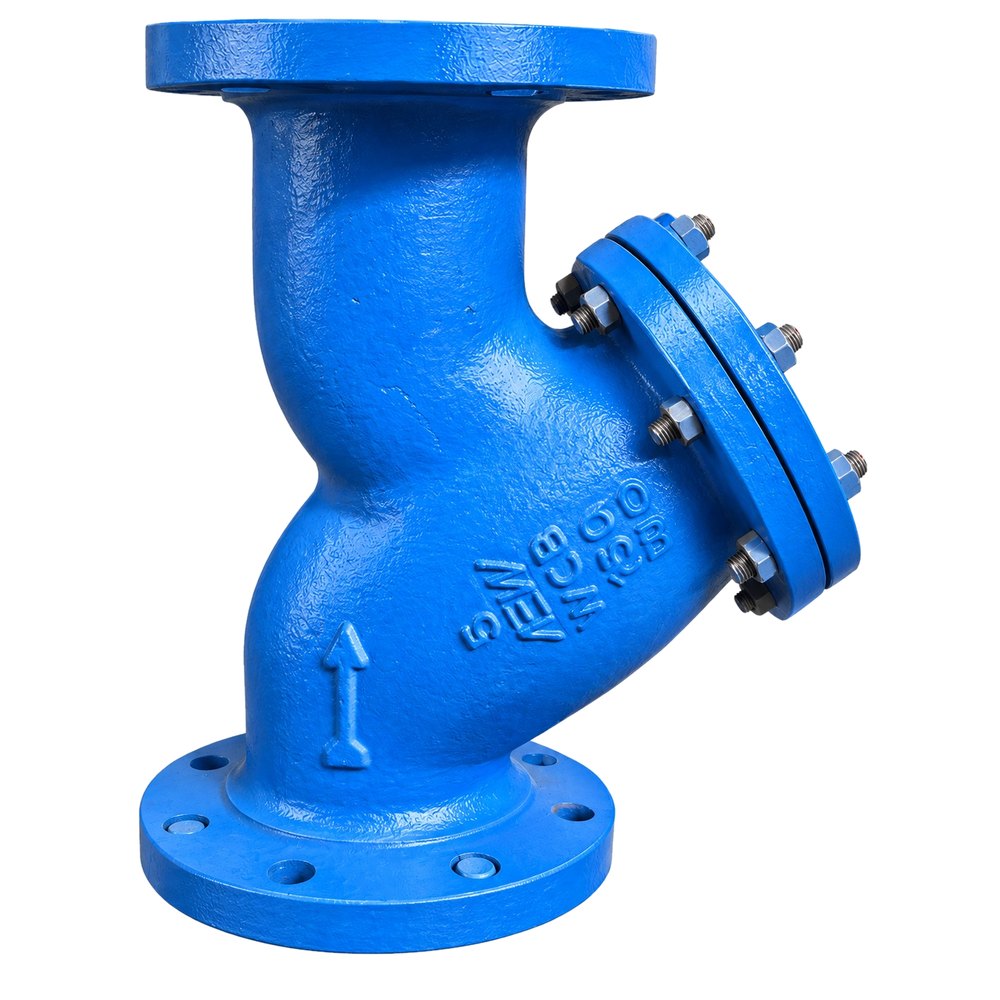
Key Features
- Effective debris removal
- Removable & replaceable screen
- Drain / blow-off arrangement available
- Suitable for horizontal and vertical installation
- Custom filtration options
Debris stays in. Clean flow passes.
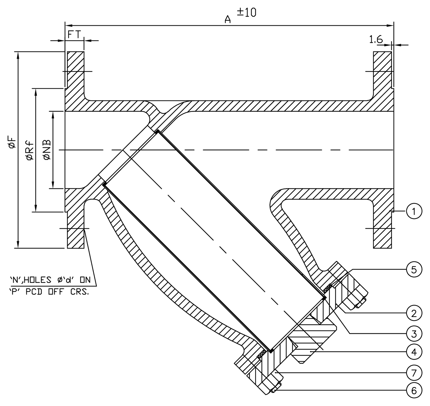
Flow enters the open end of the screen and leaves through its wall; particles too large for the mesh stay inside. For cleaning, the nuts come off and the cover and screen slide out along the leg. Drag the drawing or use the control.
In service. Flow passes out through the screen wall; the debris it catches stays inside.
Parts list
Tap a part to find it in the drawing. Illustrative DN 100 section, not to scale; the arrangement drawing and dimensions follow below.
Y Strainer, Class 150
Bolted cover with drain plug, Y-type strainer.
Parts list
- 1BodyWCB
- 2CoverWCB
- 3ScreenSS304
- 4PlugM.S. + zinc
- 5GasketGraphoil / PTFE
- 6StudA 193 Gr. B7
- 7NutA 194 Gr. 2H
Materials shown for the carbon-steel (WCB) build; CF8 / CF8M builds are in the table below. Design & mfg. code and face to face: manufacturer’s standard. End connection: ASME B16.5 R/F, Class 150.
Specify the metal to the service.
One arrangement in three standard builds, carbon steel through to 316 stainless.
| # | Part | Carbon steelWCB | Stainless 304CF8 | Stainless 316CF8M |
|---|---|---|---|---|
| 1 | Body | WCB | CF8 | CF8M |
| 2 | Cover | WCB | CF8 | CF8M |
| 3 | Screen | SS304 | SS304 | SS316 |
| 4 | Plug | M.S. + zinc | SS304 | SS316 |
| 5 | Gasket | Graphoil / PTFE | Graphoil / PTFE | Graphoil / PTFE |
| 6 | Stud | A 193 Gr. B7 | A 193 Gr. B8 | A 193 Gr. B8M |
| 7 | Nut | A 194 Gr. 2H | A 194 Gr. 8 | A 194 Gr. 8M |
Class 150
| DN · mm | NPS · in | Bore Ø NB | Face to face A | Flange Ø F | Flange thk FT | RF Ø Rf | PCD P | No. × hole Ø d |
|---|---|---|---|---|---|---|---|---|
| 15 | ½″ | 12.5 | 150 | 88.9 | 9.7 | 35 | 60.5 | 4 × 16 |
| 25 | 1″ | 25 | 160 | 108 | 11.2 | 51 | 79.2 | 4 × 16 |
| 40 | 1½″ | 38 | 200 | 127 | 14.3 | 73 | 98.5 | 4 × 16 |
| 50 | 2″ | 50 | 230 | 152.4 | 15.9 | 92 | 120.6 | 4 × 19 |
| 80 | 3″ | 76 | 241 | 190.5 | 19.1 | 127 | 152.4 | 4 × 19 |
| 100 | 4″ | 100 | 292 | 228.6 | 23.9 | 157 | 190.5 | 8 × 19 |
| 125 | 5″ | 125 | 404 | 255 | 25.4 | 185.7 | 215.9 | 8 × 22.2 |
| 150 | 6″ | 150 | 470 | 280 | 25.4 | 216 | 241.3 | 8 × 22.2 |
| 200 | 8″ | 200 | 600 | 345 | 28.6 | 270 | 298.5 | 8 × 22.2 |
| 250 | 10″ | 250 | 622 | 405 | 30.6 | 323 | 362 | 12 × 25.4 |
| 300 | 12″ | 300 | 699 | 485 | 32.2 | 387 | 431.8 | 12 × 25.4 |
| 350 | 14″ | 350 | 740 | 535 | 35.4 | 414 | 476.3 | 12 × 28.5 |
All dimensions in millimetres, as per arrangement drawing AEW/STY/150. Face to face A ±10 mm; raised face 1.6 mm. Letters match the dimensions marked on the drawing; N holes of Ø d on PCD P.
Basket Strainer
AEW Valves Pvt. Ltd. manufactures Basket Type Strainers with a bolted cover, drain plug and inlet / outlet flanges, and an SS304 40-mesh screen, for Class 150 lines from 25 to 600 mm.
- Size
- 25–600 mm · 1–24″
- Pressure
- Class 150
- Body MOC
- M.S. (IS 3589)
- Screen MOC
- SS304 · 40 mesh
- End connection
- ASME B16.5 R/F
- Testing
- API 598
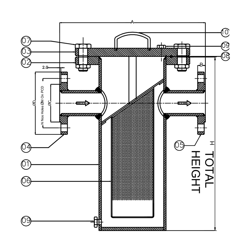
Flow drops in. Debris stays in.
Flow enters above the inclined diaphragm, drops into the open basket and leaves through its perforated wall; debris settles on the basket floor. For cleaning, the cover bolts come out, the cover lifts off and the basket follows by its tube. Drag the drawing or use the control.
In service. Flow passes out through the basket wall; the debris it catches settles on its floor.
Parts list
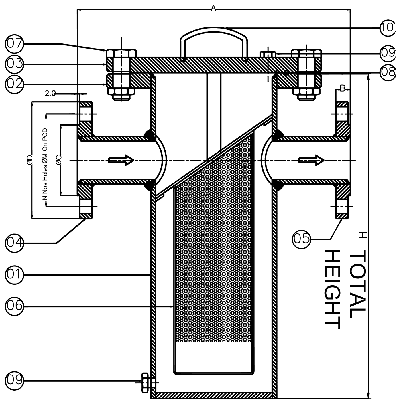
Tap a part to find it in the drawing. Illustrative DN 100 section, not to scale; the arrangement drawing and dimensions follow below.
Basket Strainer, Class 150
Bolted cover with drain plug and inlet / outlet flange, basket type strainer.
Parts list
- 1BodyM.S. (IS 3589)
- 2Top flangeM.S. (IS 3589)
- 3Body coverM.S. (IS 3589)
- 4Inlet flangeM.S. (IS 3589)
- 5Outlet flangeM.S. (IS 3589)
- 6ScreenSS304 (40 mesh)
- 7Cover nut & boltCarbon steel
- 8GasketNitrile / spiral
- 9Drain plug & vent plugASTM A105
- 10Lifting handleCarbon steel
Design & mfg. code and face to face: manufacturer’s standard. End connection: ASME B16.5 R/F, Class 150.
Class 150
| DN · mm | NPS · in | Face to face A | Total height H | Flange thk B | RF Ø C | Flange Ø D | No. × hole Ø M | PCD |
|---|---|---|---|---|---|---|---|---|
| 25 | 1″ | 200 | 250 | 11 | 51 | 108 | 4 × 16 | 79 |
| 40 | 1½″ | 260 | 300 | 14 | 73 | 127 | 4 × 16 | 98.5 |
| 50 | 2″ | 260 | 300 | 16 | 92 | 152 | 4 × 19 | 120.5 |
| 65 | 2½″ | 260 | 300 | 17.5 | 105 | 178 | 4 × 19 | 140 |
| 80 | 3″ | 300 | 330 | 19 | 127 | 190.5 | 4 × 19 | 152.4 |
| 100 | 4″ | 330 | 350 | 24 | 157 | 229 | 8 × 19 | 190.5 |
| 125 | 5″ | 400 | 425 | 24 | 186 | 254 | 8 × 22 | 215.9 |
| 150 | 6″ | 400 | 450 | 25 | 216 | 279 | 8 × 22 | 241 |
| 200 | 8″ | 465 | 550 | 28.5 | 270 | 343 | 8 × 22 | 298.4 |
| 250 | 10″ | 515 | 700 | 30 | 324 | 406 | 12 × 25 | 362 |
| 300 | 12″ | 575 | 800 | 32 | 381 | 483 | 12 × 25 | 432 |
| 350 | 14″ | 680 | 900 | 35 | 412.7 | 533.4 | 12 × 28.6 | 476.2 |
| 400 | 16″ | 750 | 1000 | 36.5 | 469.9 | 596.9 | 16 × 28.6 | 539.7 |
| 450 | 18″ | 850 | 1100 | 40 | 533.4 | 635 | 16 × 31.7 | 577.8 |
| 500 | 20″ | 1000 | 1200 | 43 | 584.2 | 698.5 | 20 × 31.7 | 635 |
| 600 | 24″ | 1200 | 1300 | 47.6 | 692.1 | 812.8 | 20 × 34.9 | 749.3 |
All dimensions in millimetres, as per arrangement drawing AEW/BSKT/150. Letters match the dimensions marked on the drawing; N holes of Ø M on the PCD.
Technical Specifications
Cast or forged, sized and specified to the line: screen, end connection and material selected to the service.
| Parameter | Detail |
|---|---|
| Size | ½” to 24″ and larger on request |
| Pressure Rating | Class 150 / 300 / 600 / 900 and higher* |
| Body Design | Cast / Forged construction depending on size and rating |
| Body MOC | Cast Iron / Ductile Iron / Carbon Steel / SS304 / SS316 / CF8 / CF8M / Duplex / Special Alloys |
| Screen MOC | SS304 / SS316 / Duplex / Special Alloys |
| Screen Type | Perforated / Mesh / Combined |
| End Connection | Flanged / Screwed / Socket Weld / Butt Weld* |
| Drain Connection | Available as required |
| Gasket | Graphite / PTFE / CNAF / Application-specific |
| Medium | Water / Air / Gas / Oil / Steam / Chemicals & other process fluids |
| Operation | Manual cleaning / Drain or Blow-off arrangement |
| Temperature | Application and material dependent |
* Higher pressure ratings and additional end connections are available on request.
Technical Specifications
Standard construction, as per arrangement drawing AEW/BSKT/150.
| Parameter | Detail |
|---|---|
| Size | 25 to 600 mm (1″ to 24″) |
| Pressure Rating | Class 150 |
| Construction | Bolted cover with drain plug and inlet / outlet flange |
| Body MOC | M.S. (IS 3589) |
| Screen MOC | SS304 (40 mesh) |
| End Connection | ASME B16.5 R/F, Class 150 |
| Drain Connection | Drain plug & vent plug, ASTM A105 |
| Gasket | Nitrile / Spiral |
| Design & Mfg. Code | Manufacturer’s standard |
| Inspection & Testing | API 598; hydro test, shell 30 kg/cm² |
Gallery
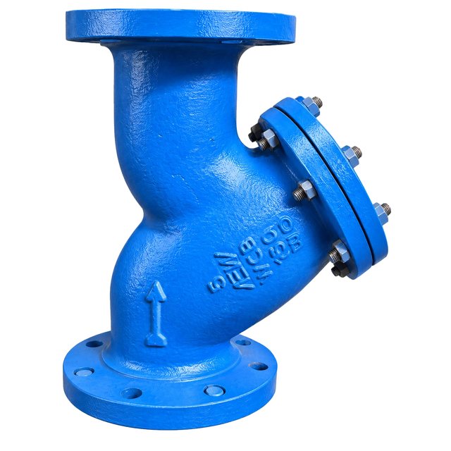
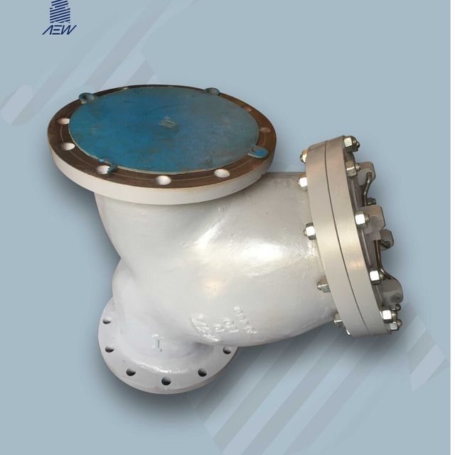
Cast, machined, and shipped.Made at the Shahibaug works in Ahmedabad, trusted on GAIL, BARC, Adani and Asian Paints lines.